
Bright Field Imaging and Dark Field Imaging
Bright Field/ Dark Field:
Video on Bright Field Imaging and Dark Field Imaging
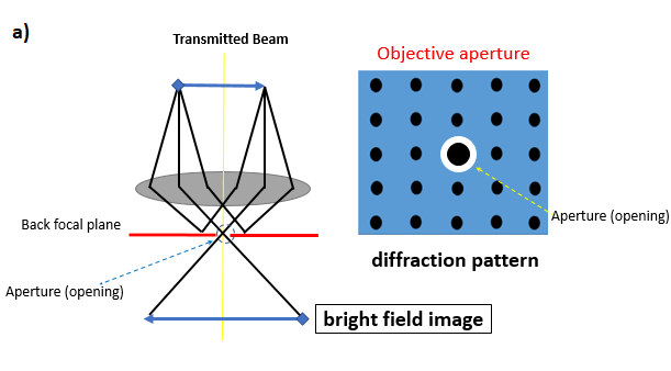
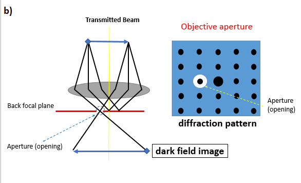
Fig. 1: a) direct beam is allowed to pass through for forming a bright field image, and b) diffracted beam being allowed to pass through in order to form dark field image.
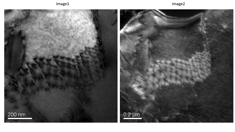
Fig. 2: TEM Micrographs of a ceramic material showing a) bright field (Image1), and b) dark field (Image 2).
Amplitude contrast is obtained when there is preferential absorption of electron due to higher thickness or its scattering (or diffraction). Amplitude contrast can be classified into: (i) mass-thickness contrast, wherein high mass (or thickness) scatters the incident electrons to higher angles, which go undetected by the objective aperture, or (ii) diffraction contrast, wherein the electron beam gets selectively diffracted (or appropriately oriented crystalline region) of the specimen. Phase contrast is obtained when the electron interaction with matter shifts the waves of similar thickness materials (but of different phases or orientation). Thus, this contrast can also be utilised to separate out the different density or regions with different atoms, or even with different atomic density (or planar density).
The selection of the direct beam or diffracted beam is analogous to capturing the information concerning that particular feature the beam has interacted with. If certain crystals have diffracted the incident beam, the scattering will occur as per Bragg’s condition. But, the orientation of each feature in similar fashion will scatter it at same angle. Thus, imaging from one diffracted beam (keeping the aperture and allowing it to form an image) may show few features bright (and the field will be dark). Important point to note here is that if another diffracted beam is allowed to pass through, then some other features will appear bright (and the field will remain dark). In summary, each diffracted spot is appearing due to specific orientation of certain features, which will start to appear bright if that diffracted beam is allowed to form the image. And in bright field mode, those features may or may not appear bright.